Page Setup View
1. Unit Objectives
In this unit we will continue building on the Offer Letter by enhancing the physical look using lines. We will also demonstrate the cut and paste feature, creating a header and adding text to it. In addition, we will be creating a footer that will contain text and a system variable of page number.
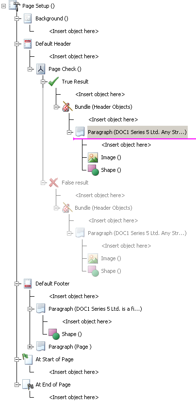
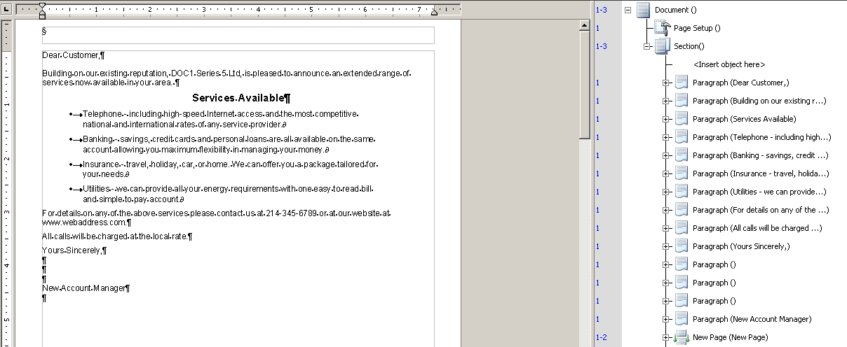
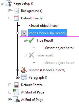
2. Page Setup View
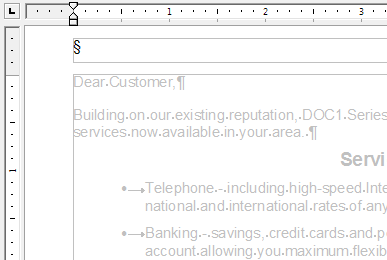
The Page Setup View contains logic that is performed every time a document generates a new page. The headers, footers and backgrounds are designed and edited in this view. Text and images placed in these sections are grayed out to the document view.
The Page Setup is made up of 8 main components:
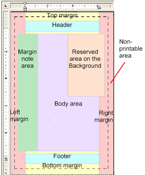
- 1. Header: Is placed within the top margin of every desired page. Not every page is required to have headers. Size and content of the header can be controlled by conditional logic.
- 2. Footer: Is placed within the bottom margin of every desired page. Not every page is required to have footers. Size and content of the footer can be controlled by conditional logic.
- 3. Non Printable Area: Is an area where printers cannot print.
- 4. Top/Bottom Margins: Are perimeters around the edge of the page.
- 5. Background: Is a layer in the document which can be used either to add content ‘behind’ the main body -e.g. to provide watermarks.
- 6. Reserved Area: It is added in the background layer to make that part of the page unavailable for content in the document view.
- 7. Body: The primary area where content is added to document designs is known as the body. Content within the body will flow onto new pages as required.
- 8. Margin Notes: Is a defined space in the background which is used to control positioning of margin notes. Multiple margin note areas can be defined in the Page Setup view.
3. Import Image
There are two ways images can be loaded in a publication; through the Work Center repository or the local file system. If you load an image from the local system it will be automatically added to the repository, but will only be available to the current document unless you set it public. You don’t have to worry about this for images loaded via the Work Center repository.
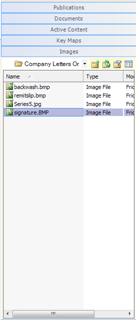
We are going to import images into our Work Center repository. We can select multiple images to import at the same time by using the Shift or Ctrl keys.
4. How to a Create Header
Logic can be added in this section to adjust the size of the header section or change the content. Headers can be set to show up on all, even, or odd pages.
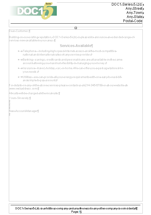
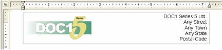
In this section we will be creating the header area, adding a company address and corporate image to it.
5. Creating a Bundle
A bundle allows us to group logic making it easier to reference, manipulate and trouble shoot.
We are going to create a Bundle and store all the header items.
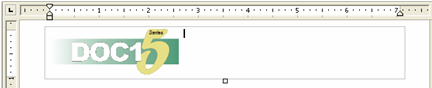
6. Inserting an Image in the Header
We are going to insert images from our Work Center repository. The company address and image will be placed in a bundle.
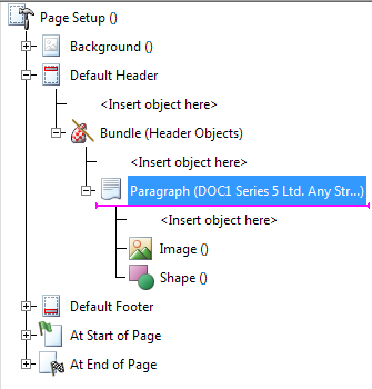
- 1. In the logic map, mark your insertion point at Bundle (Header Objects) <Insert object here>.
-
The insertion point is a marker used in the logic map that indicates the object after which the next object will be added.
- 2. From the main menu select Insert/ Presentation Object/ Image.
- 3. Navigate to the folder that contains the resources.
- 4. In the Company Letters project folder, double-click Series5.jpg.
Next we are going to add some shape properties to the images so that any text placed will wrap to the right of it.
- 1. From the main menu select Format/ Shape.
- 2. Select the Layout tab.
- 3. Flow, click the Fixed radio button.
- 4. Click the Right runaround icon.
- 5. Click OK.
The company address will be placed to the right of the header.
7. Lines
By using the shape drawing tool simple graphics can be created. In this section we will draw a line in the header.
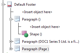
8. How to Create a Footer
Logic can be added in this section to adjust the size of the footer section or change the content. Footers can be set to show up on all, even, or odd pages.
In this section we will be placing a disclaimer, system variable for page number and a line.
- 1. From the main menu select, Insert/Presentation/Line.
- 2. Hold down the shift key.
- 3. Click and drag to draw a line the width of the footer.
- 4. In the document mark your cursor in the Footer section.
- 5. Press Enter.
- 6. Set font to, Arial, 11, Regular, Align Center.
- 7. Type, DOC1 Series 5 Ltd. is a fictitious company and any likeness to any other company is coincidental.
-
8. Press Enter.
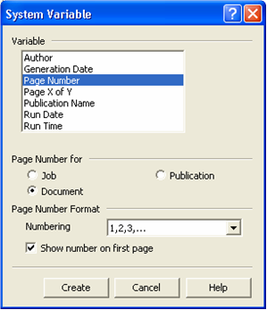
9. System Variable - Page Number
System variables allow you to access information from the production environment; for example, the number of pages generated by a publication, the time and date the production job was started.
In this section we will be creating a system variable for page number.
- 1. From the main menu select Insert/ Field/ System Variable.
- 2. Select Page Number.
-
3. Page Number for, click, Document radio button.